


 Chrome OS VM running under Windows 7.


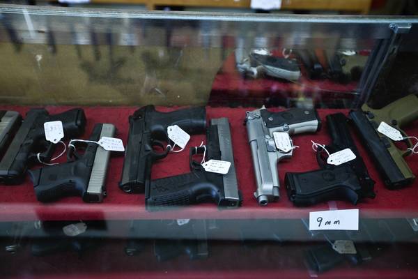
The city must now decide whether to appeal the ruling or rewrite the part of its gun ordinance that bars individuals convicted of even misdemeanor offenses from possessing a firearm in their home for self-defense. (Zbigniew Bzdak, Chicago Tribune / February 28, 2012)
|
Chicago's firearm ordinance took another blow Tuesday when a federal judge ruled that the section banning permits for people convicted of unlawful use of a weapon is vague and unconstitutional.
The city must now decide whether to appeal the ruling or rewrite the part of its gun ordinance that bars individuals convicted of even misdemeanor offenses from possessing a firearm in their home for self-defense.
The ruling came in a lawsuit filed by Shawn Gowder, who claimed his constitutional right to bear arms was violated when he was denied a firearm permit two years ago because of a misdemeanor conviction for possessing a gun on a public street.
The lawsuit, backed by the National Rifle Association, is one of at least five cases pending against the city's gun ordinance, which was passed in 2010 just days after theU.S. Supreme Court struck down the city's 28-year ban on handguns. The Illinois State Rifle Association also filed a brief in support of Gowder.
The decision by U.S. District Judge Samuel Der-Yeghiayan addresses only a part of the ordinance that relates to applicants who have been convicted of unlawful use of a firearm. Federal lawsuits are still seeking to overturn the city's ban on retail gun stores and to remove restrictions forbidding guns from yards and on front porches.
City officials said they are reviewing the ruling and will advise police on how to proceed with enforcing the law. Since it applies only to one provision of the ordinance, a City Hallofficial said, city attorneys do not believe the ruling will have a significant impact on the entire ordinance.
The judge ruled that the city's ordinance does not adequately define "unlawful use of a weapon," noting that it can mean different things in different jurisdictions.
"There is something incongruent about a nonviolent person, who is not a felon but who is convicted of a misdemeanor offense of simple possession of a firearm, being forever barred from exercising his constitutional right to defend himself in his own home in Chicago against felons or violent criminals," Der-Yeghiayan wrote.
"The same Constitution that protects people's right to bear arms prohibits this type of indiscriminate and arbitrary governmental regulation," he continued. "It is the opinion of this court that any attempt to dilute or restrict a core constitutional right with justifications that do not have a basis in history and tradition is inherently suspect."
Gun rights advocates hailed the ruling as a victory for Second Amendment rights.
"The only thing Mr. Gowder did was to own a firearm. As a result, he was treated like a criminal by the city of Chicago when all he did was exercise his fundamental Second Amendment right," said Stephen Kolodziej, a Chicago attorney representing the plaintiff. "We think the city of Chicago's actions in denying Mr. Gowder a firearm permit were punitive and draconian as well as violative of his constitutional right to keep and bear arms."
Gowder was denied a firearm permit in 2010 because of a 1995 misdemeanor conviction for possession of a firearm on a public street. At the time of his conviction, the offense was classified as a felony, but the Illinois Supreme Court in 1999 struck down the Safe Neighborhood Act, which classified simple possession of a firearm as a felony, and made it a misdemeanor.
Gun advocates have long opposed laws that summarily banned those even with convictions for nonviolent felonies from obtaining a legal weapon. They have argued that several factors should be considered, including the nature of the prior conviction and the length of time that has passed since it occurred.
Brian Koukoutchos, a Manderville, La., attorney who also represents Gowder, said: "Some thought needs to be given to what the nature of the crime is."
"You have to be careful when you allow run-ins with the law to automatically strip someone of their rights," he said.
Twitter @ltaford


